I spent three days or so recreating the original sand robot from scratch. I have access to a much larger 3D printer now, so I'm able to fully print everything in one piece, except the acrylic that the sand rests on.
If you want to read more about the original robot, check out the article linked below
Originally, the robot used a 2-DoF SCARA arm to maneuver the ball around, however, I didn't like how much vertical space was used up by this mechanism.
The robot uses a central gear with 238 teeth to drive the rotation angle. It's driven with a stepper motor off to the side with a 500mm timing belt. They're spaced appropriately to keep adequate tension.
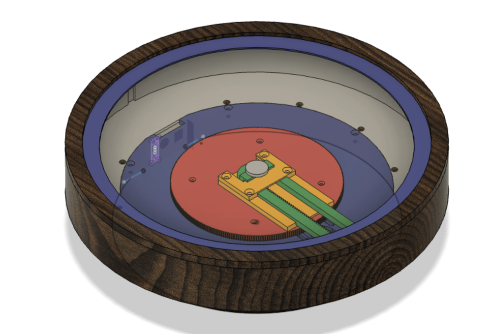
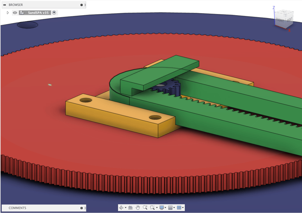
The linear axis rotates off of the central gear and is a basic rack and pinion-type drive. The stepper motor in the center goes all the way through the central gear and has the pinion gear attached to the top.
I was honestly really surprised at how well it was turning out so far!
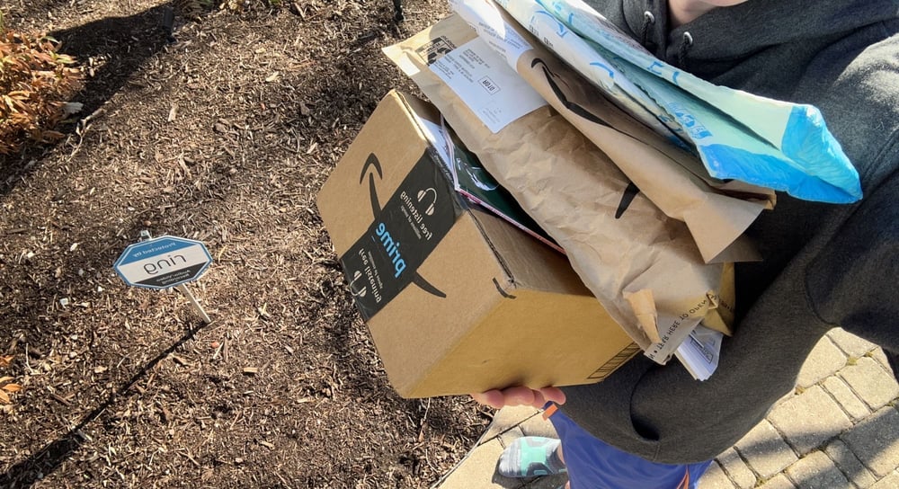
While I was waiting for the main housing to finish printing, the remaining components came in the mail.
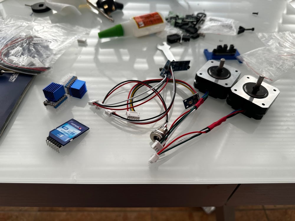
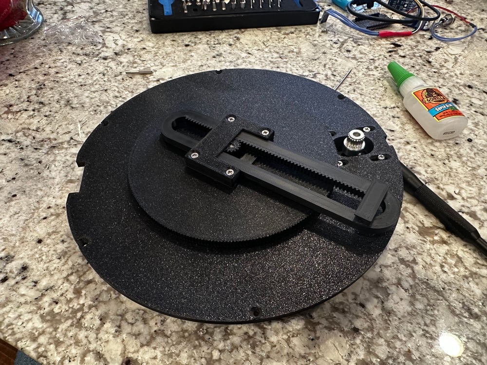
Since the robot has no "stop points," I couldn't use typical end stop sensors. I decided to use magnetic sensors mounted on the base, with magnets embedded in the printed pieces to determine the home position.
There's also an SD card to store pattern files, a pair of TMC2209s to drive the steppers, and a TSL2561 breakout board to sense ambient light.
And of course, I'm using my favorite microcontroller to power this thing, the humble dual-core ESP32!
I ordered a large kit of different JST connectors so I would be able to easily connect everything up to the circuit board, which was also currently on the way from JLCPCB. It's a pretty bare-bones design, and I just used one of the spare boards that I had left from the Coffee Table project.
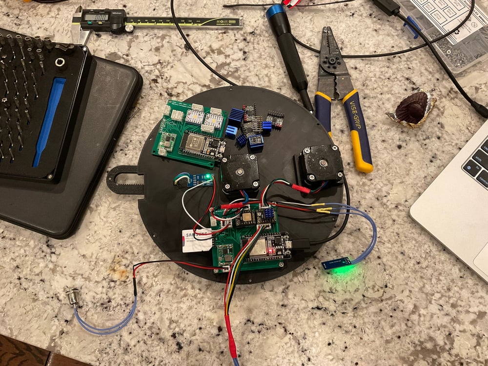
Even though I've used the same Trinamic drivers in other projects before, I ended up frying SIX of them simply because I forgot to plug in the motors... They're all shown on the top side of the robot here :p
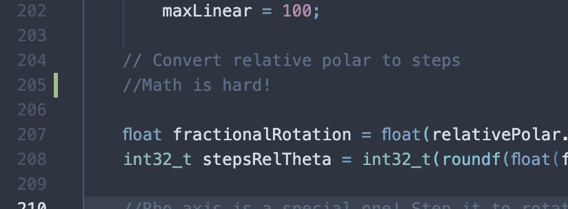
I was lucky enough to have most of the firmware written already from the coffee table project, however, I had to design and implement a new abstraction layer for this robot's new mechanism design.
I'll skip the boring parts, but essentially, I needed to convert the Cartesian coordinates sent by the higher-level classes into polar coordinates, and then use a series of conversions to find the number of steps needed to move the gear. For the rho (linear) axis, it was a bit weirder. The movement of the rotary axis affected the position of the rho arm, so I had to compensate for this in my calculations and compensate for it again when the robot recalculates its Cartesian position based on the current step counters around 20-30 times a second.
The motion abstraction code is in the RobotSandTableRotary.cpp file in the repository.
 GitHub • acvigue
I used a high-density SK6812 RGBW LED strip to line the outer edge of the upper area of the robot. I was using FastLED, so I had to create an extension of the CRGB class with an extra byte for the white value and trick the driver into sending these extra bytes
if (_ledIsRGBW) {
        _leds = new CRGBW[_ledCount];
        _ledsRGBTemp = new CRGB[ledCount];
        _ledsRGB = (CRGB*)&_leds[0];
        FastLED.addLeds<WS2812B, LED_PIN>(_ledsRGB, getRGBWsize(_ledCount));
    } else {
        _leds = new CRGBW[_ledCount];
        _ledsRGBTemp = new CRGB[ledCount];
        FastLED.addLeds<WS2812B, LED_PIN>(_ledsRGBTemp, _ledCount);
    }
cpp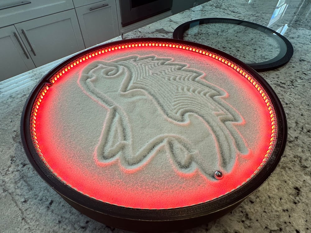
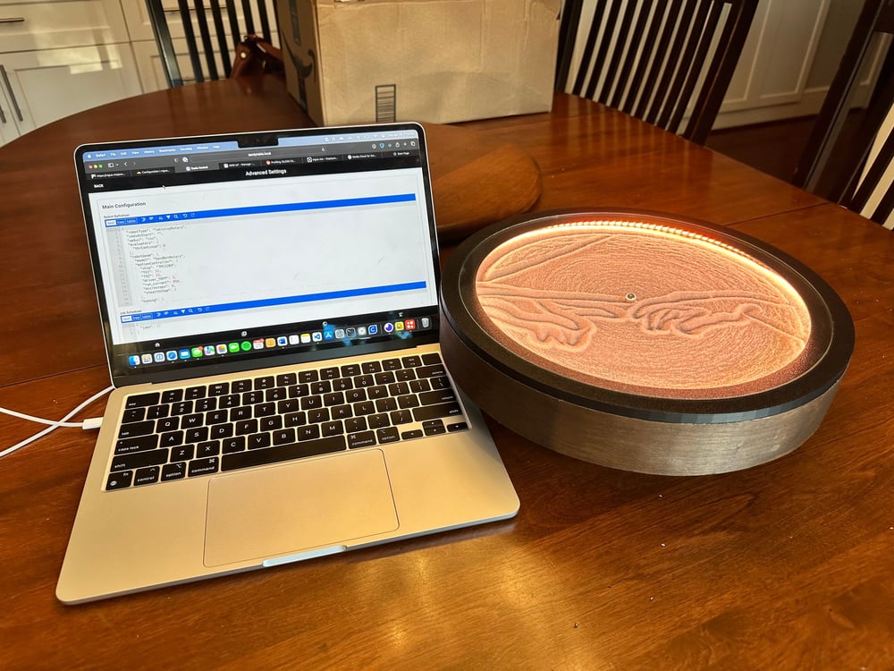
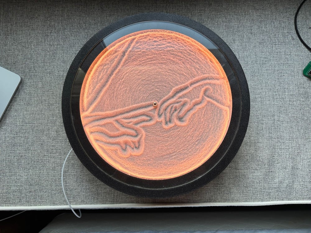
The lights reflect off of the underside of the glass holder back down towards the center of the sand, and it results in a much more even glow:
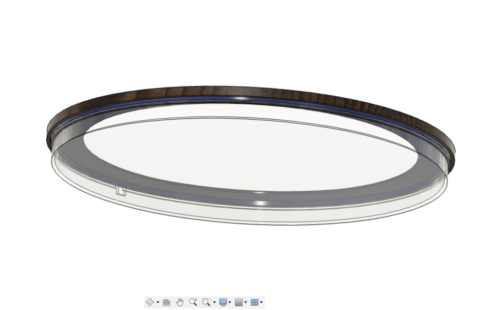
I ended up ditching the acrylic and decided to split the upper portion of the robot into 3 parts. One would be the sand bed that was fixed into place by a lip on the outer enclosure. The light strip would be mounted on the sides of this. The glass holder was then split into two pieces, one that went under the glass, and one that went around it. I did this to minimize overhangs in the printed parts to keep an even surface texture.
I spray-glued some black velvet to the top side of the sand bed to add contrast with the sand, and to prevent rolling noises.
I completely rewrote the original Vue SPA codebase that I used for the old table's web app, upgraded it to Vue 3 in the process, and added a real Pinia datastore. The app fetches information from the table using a combination of REST and HTTP Server-Sent Events.
GitHub • acvigueThis is great, except I'm going to college where the Wi-Fi-connected devices have client isolation. I wouldn't be able to control the robot then. I had to figure out a way to remotely connect to the device without any intermediaries between the end device and the robot besides one central server.
Or, I just needed to figure out a solution to the problem... And, I really didn't want to write an entire MQTT api for this.
Enter, WireGuard.

WireGuard is a blazing-fast, secure VPN protocol, and the ESP32 implements the LwIP API for connecting to TCP/IP networks. Using a combination of the knowledge of the cryptography behind WireGuard, mbedTLS, and the creation of an additional network driver for the ESP32, I was able to get the program to manage the lifecycle of a WireGuard connection.

Look at that! A virtual IP address for the ESP32!
I have the ESP32 connected to a WireGuard server running on an AWS EC2 instance, and the robot has an IP on this internal VPN network. This server then proxies that IP through Nginx, through a CloudFlare Tunnel, and then it is protected by CloudFlare Zero Trust to prevent unauthorized access.

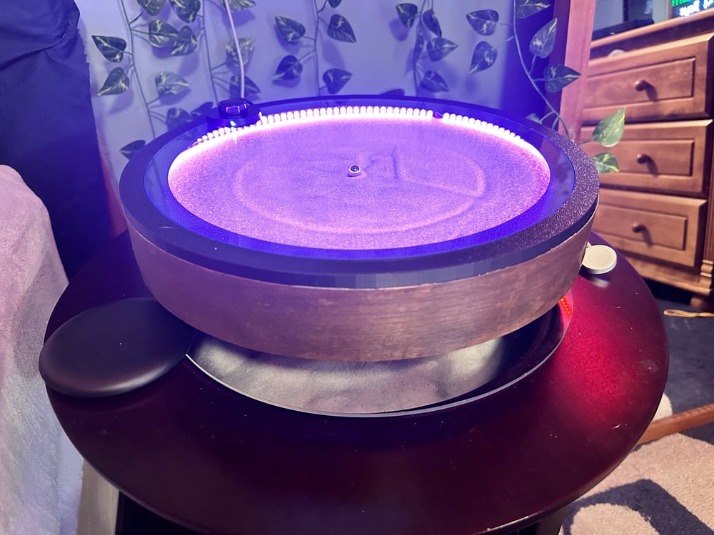
I wanted to have the exterior of the robot have a wooden appearance, so I spent four hours applying a roll of real walnut veneer that had a backing of hot-melt glue with a clothing iron. The first 8 tries didn't go too well, but it's on well enough now and I gave it a good stain.
As with the larger coffee table project, this took a lot longer than I expected. I ran into many issues with the robot bearing and eventually redesigned the entire central shaft to use a secured lazy-susan bearing.