
I've always wanted to make my own Nixie tube clock. Nixie tubes were extremely popular in the 50s and 60s and were the precursor to LED and VFD displays. I love the idea of driving old and forgotten technology with modern components.
According to the date code stamped on the back, the tubes I used were manufactured in April of 1983.
But, I forgot about the idea for a few years until I was scrolling through eBay and found a set of six NOS (new, old-stock) IN-14 Nixie tubes for $99. I couldn't pass these up, so I bought them and immediately started brainstorming how to use them.
Most Nixie clocks use the SN74141 IC or a variant thereof, it's a dedicated BCD decimal decoder designed specifically for Nixie tubes. That chip is starting to show its age and I would need 7 of them to drive all 64 cathodes across the six tubes.
I wanted to use the four inner decimal points as "colons" bringing the total cathode count to 64 (6*10 + 4)
And, of course, big Microchip came out with bought out a company that designed a 32-bit shift register specifically for driving high-voltage loads, the HV5222. I could even control it through SPI! Two of these chips in series would give me exactly 64 controllable outputs, with just 3 control pins. They do use a 12V logic level, and the microcontroller I wanted to use sported a 3.3V logic level, so a few transistors solved that issue.
Another big issue with driving Nixie tubes is the power supply. They require around 170V at almost exactly 2.5mA, or you risk prematurely damaging the tubes. Most clocks use an extremely inefficient (15%!) 555-timer-based design to boost the input voltage up to this level. I decided to use the LT3750 flyback converter paired with an extremely efficient switching MOSFET, which ended up giving me an average efficiency of (80-85%.)
Lately, I've been on a kick to reduce the amount of "non-standard" power supplies I have laying around the house.
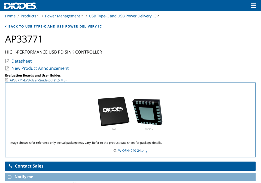
And, because of this, I just had to overcomplicate the entire thing even further by adding USB-C power delivery! Sparkfun recommends using the STUSB4500, but I really really didn't want to go down the rabbit hole of I2C configuration profiles. The AP33771 IC offers the same level of control just by using pull-up and pull-down resistors.
Since I only needed a static voltage of 15V, I went with the AP33771.
I started the design process by creating the schematics that I was going to base the circuit board off of. I used Altium Designer 24. I used Altium's KiCAD import tool to import the footprint for the IN-14s from a library I found online.
The 15V to 5V/3.3V stepdown is controlled by a TPSM33625 buck converter paired with a bog-standard LDO regulator.
And, yes, the entire thing is driven by an ESP32. At this point, I fail to believe that there's a more successful embedded platform to develop with.
I think I spent a few weeks in this design stage before I was comfortable enough with the circuit design.
I strongly believe that PCB design is a science, however, it can also be a form of art if done well. Even though there are only ~100 components to be placed on this board, I spent a ton of time aligning each one and tried to make it aesthetically pleasing because I wanted to put this project on display in a clear acrylic case.
The centerpiece of the board is obviously the Nixie tubes, but located just behind those, we have two HV drivers. The high voltage section is very obviously marked off, over on the side.
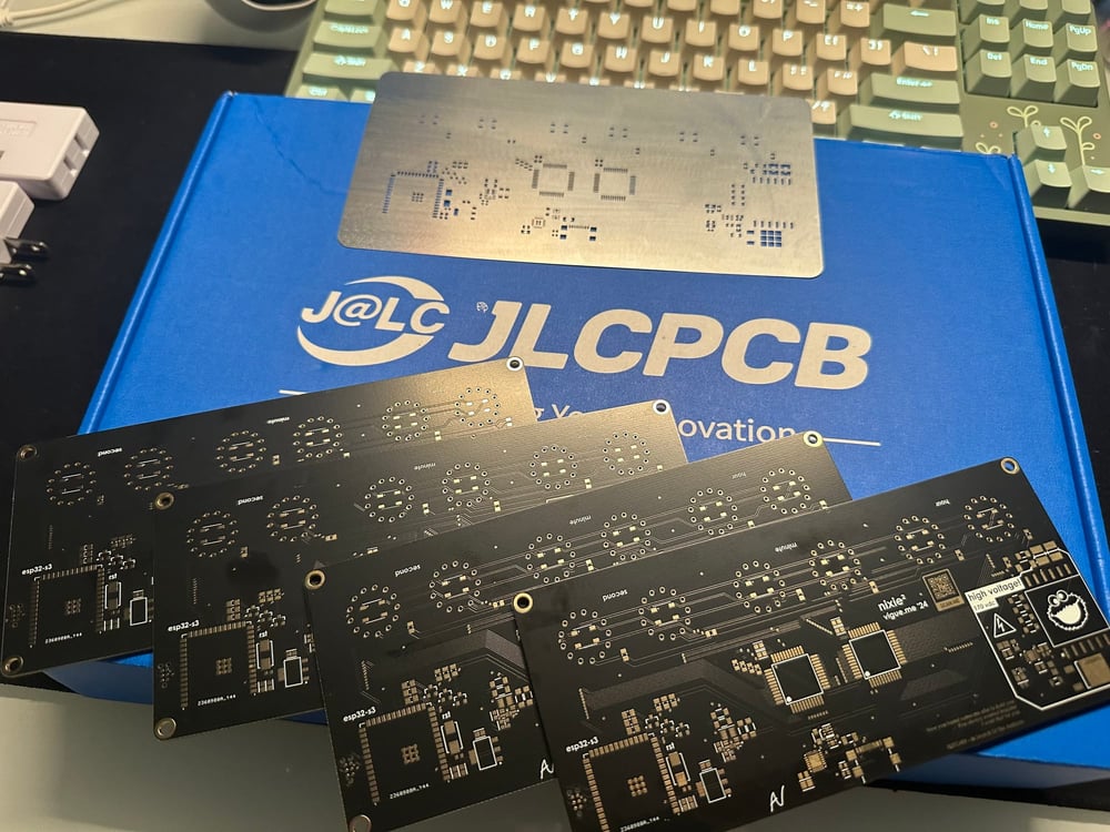
I also usually stick with using HASL surface finish and purple solder mask, but that didn't look very nice in the online viewer, so I opted to do black solder mask with ENIG finish, and I'm very glad that I did!
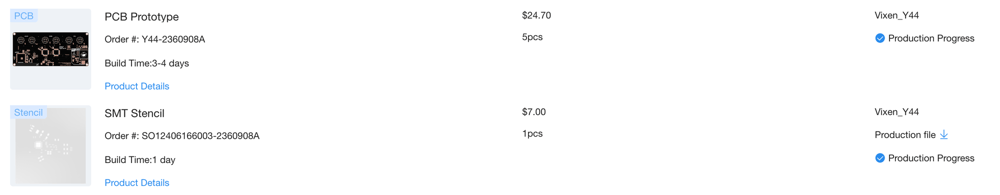
The boards were manufactured by JLCPCB using their standard 2-layer service. I ordered 5 copies, along with a SMT stencil for just under $45 including shipping. It took just under a week for them to arrive, and as always, I was really impressed with the quality!
If you'd like to make your own, here is a coupon code that you can use for a discount on the PCBs.
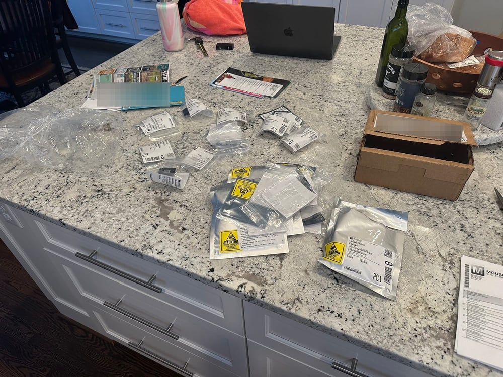
I also took this time to order the electronic components from Mouser. They were the only distributor that had the HV5222 in stock.
Shameless plug: I've also had amazing interactions with their customer service team on multiple occasions!
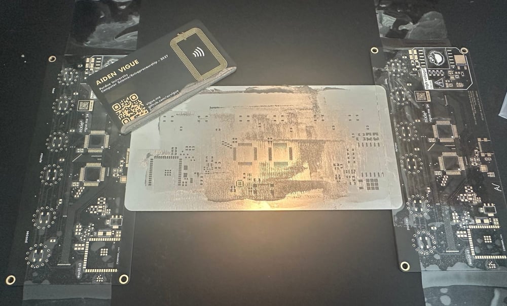
My favorite part! I always start this process by using the stencil to spread out some solder paste. I've found that my business cards are the perfect size and thickness to use for this.
I then placed all the components on the board, and then put them into my repurposed Target toaster oven that I use as a reflow oven.
I plugged the board in and... nothing happened. Apparently, I need to relearn my metric prefixes because I ordered a 1 million ohm resistor when I was supposed to order a 1 milli-ohm resistor (0.01 ohms.) So, I bit the bullet and paid for overnight shipping.
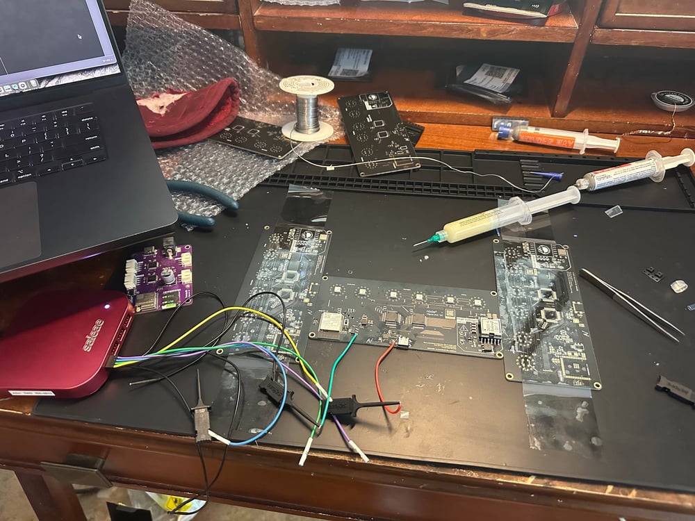
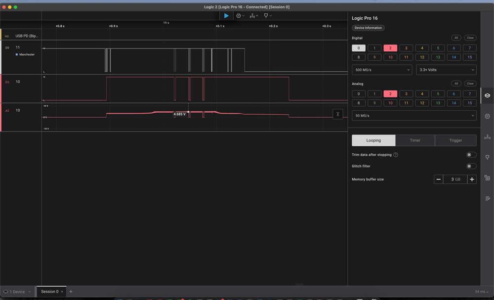
I used my Saleae logic analyzer to confirm that the issue was due to the AP33771's OVP protection kicking in.
In the meantime, I bypassed the USB-C power circuit and was able to test the DC/DC step-up and step-down to 5V. The lights also worked once I figured out that I put them on backward.
I wanted to use ESPHome for the firmware, and there wasn't an existing component for HV5222 support. I had to write my own component, similar to what I did for my Levoit air purifier conversion.
But, Microchip decided to make things difficult and use a non-standard interface for these ICs. That and my desire to use SPI to drive them led to many issues. There was also an issue where the ESP32 spat out random waveforms whenever I tried to use the hardware SPI peripheral.
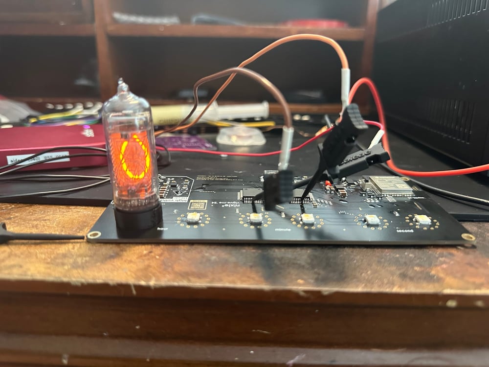
I got much better luck when I switched to bit-banging the interface. I also used the Saleae here to help me determine the proper SPI mode. These chips latched data on the rising clock, so the default MODE3 was incorrect.
I tested with only one tube soldered onto the board.
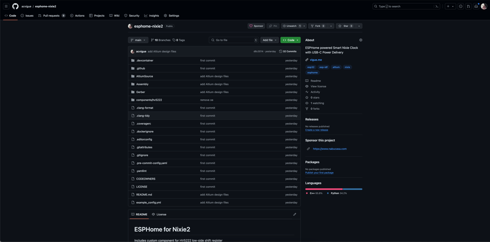
I've created a GitHub repository for the PCB design files and the ESPHome configuration for the clock. It's fully configurable from Home Assistant and the tubes can even be dimmed.
The repository also has the compiled Gerber outputs and component BOM files to order your PCBs. The CPL Pick N' Place file is also available if you'd rather have your boards preassembled.
 GitHub • acvigue
For more detailed instructions, I've also written this project up on my Instructables page