
I've always been interested in home automation and with the rise of the new Matter/Thread standard for device connectivity, I decided that it would be a great time to design a smart home hub that was (hopefully) future proof for at least the next five to ten years.
Since I'm going to college, I needed it to be remotely connected to my instance of Home Assistant running back at home.
The most common protocols used in smart home products today are Zigbee, Z-Wave, Bluetooth, and Thread. The main goal of this project was to integrate all of these different protocols into one customized and extendable board that could work with Home Assistant or any other compatible automation software.
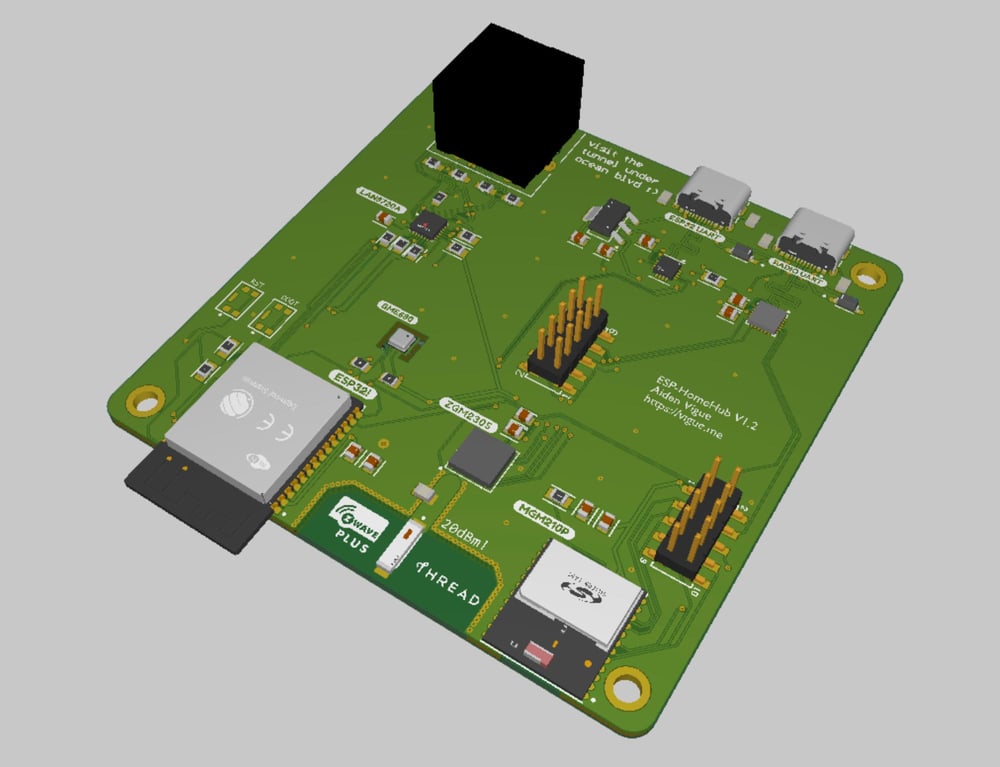
Looking around online, I found that Silicon Labs had just released their 800-series ZWave chipsets, specifically the ZGM230S, but there wasn't much information out about it yet. I'm currently using a 500-series radio, so this would be a signifigant performance upgrade. On the Zigbee/Thread (802.15.4) side of things, I was going to use the same module used on the Home Assistant Yellow, the MGM210p.
To integrate the hub into Home Assistant, I planned to use an ESP32 running ESPHome to create TCP serial bridges to each of the radio modules. I also wanted to have some sort of environmental monitoring sensor attached to the board as well.
I used Altium Designer 23 to create the PCB and schematics for this project, as I prefer how it integrates with online component databases without using plug-ins like SnapEDA or Ultra Librarian.
I was digging around the ESPHome documentation, and realized that the ESP32 also has an Ethernet MAC peripheral! It just required a PHY interface chip and supporting components.
 ESPHome
 However, the GPIO pins used for Ethernet were hard-coded due to the pin mux restrictions on the original ESP32. I was already using the majority of these pins for other functions, such as the radio UARTs, so I had to re-route the majority of the circuit board...
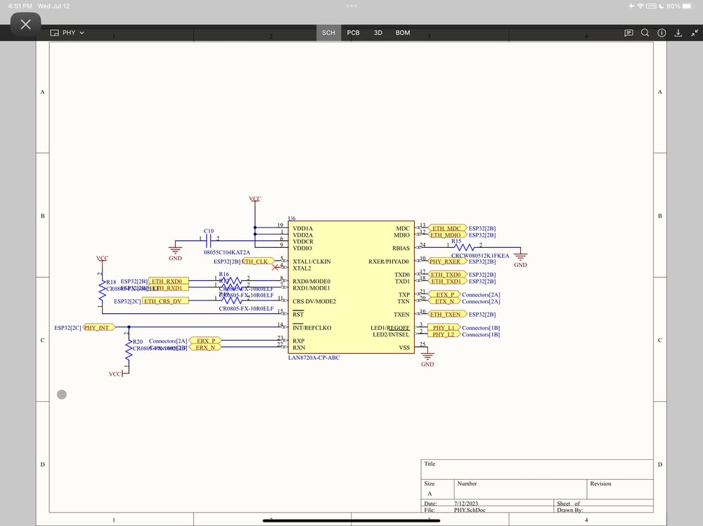
I settled on using the LAN8720A chipset from Microchip, as it was relatively low-cost and unlike most other PHY interfaces, it came in a "easy to solder" QFN28 package, and had all the Ethernet LED logic integrated inside. I saved $0.04 on resistors. 🥳
Here's the link to a PDF of the schematics:
 GitHub • acvigue
One of the main goals of this hub was to make it future proof, and since I wouldn't need it to be connected remotely forever, as I'm not planning to be in college for the rest of my life, I wanted alternate ways to communicate with the radios. Using yet another IC from Silicon Labs, the CP2105 dual channel USB-UART converter and a few diodes, I added an extra USB-C port that provided direct communication to both of the radio modules, essentially creating an optional bypass of the ESP32.
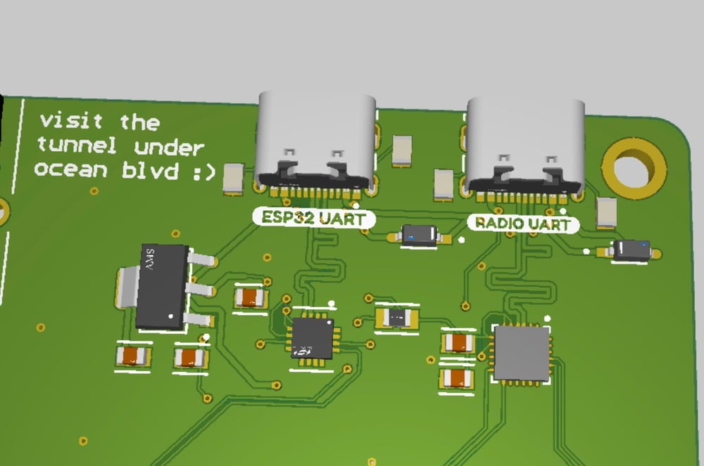
The diodes were used to isolate the VBUS lines from each USB port to avoid triggering any "weirdness" caused by having an unused bridge connected to the radios.
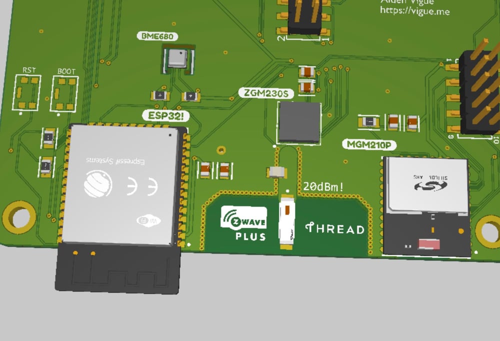
Since Espressif STILL hasn't come out with a readily available SoC capable of connecting to 5GHz networks, there was going to be a lot of activity in the 2.4GHz band from both the Wi-Fi/BLE from the ESP32, and Zigbee/Thread on the MGM210p. I really didn't care about ZWave since I could just crank up the TX power to 20dBm and it resided on a different, sub-GHz frequency.
I put the ESP32 and the MGM210P as far away from each other as possible and used extensive via stiching for the Z-Wave antenna keepout area. I was hoping that since it was between the other two antennas, this would help with possible interference.
I ended up having to make two versions of this PCB since I blindly attempted to create a QFN44 footprint for it, not realizing that the pads were actually inset. I think I spent a good four or five hours attempting to solder that part before I realized it wouldn't ever work. 😬
I tried my best to use the PCB impedance calculator provided by the board manufacturer to tune the Z-Wave antenna trace to 50 ohms, and I followed the reference design to use a 2.2pF tuning capacitor to ground. In practice, this worked really well, I was able to communicate with a Long Range class device almost 1.4 miles away, almost aligning with the specifications.
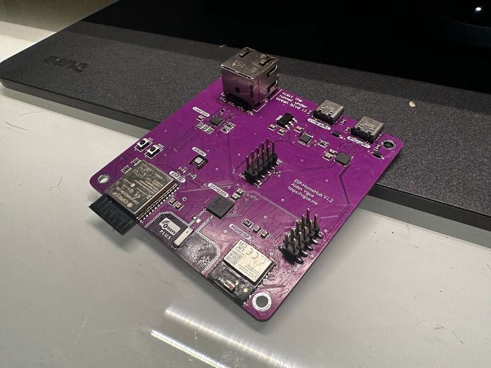
I ordered the PCBs from JLCPCB with a purple soldermask color and also had a stencil printed so I could use solder paste and my reflow oven since most of the chips were QFN. The components were ordered from Mouser as they don't enforce MoQs which is great since I'm only making three of these boards.
The boards & stencil took less than a week to arrive at my door, and I quickly set up a makeshift jig to hold everything in place with duct tape! I was really happy with the quality of everything, especially the very fine pads on the stencil.
I just used an old PVC card to squeegee the solder paste around on the stencil and then placed the components on the board with tweezers. The solder paste I used is ChipQuik No Clean from Amazon, and I've never had issues with it.
Like my Smart Tiles project, I reflowed these PCBs in the converted toaster oven, using the Reflow Master control board that I built following the instructions here.
I assembled and reflowed three of these boards.
Much unlike the PCB version one, where nothing on the board worked, due to the Z-Wave chip shorting everything out from a footprint issue, this one was more of a success! The CP2102 and CP2015 serial bridges worked great, and esptool could see the ESP32, however I didn't yet have a way to test the functionality of the radio modules.
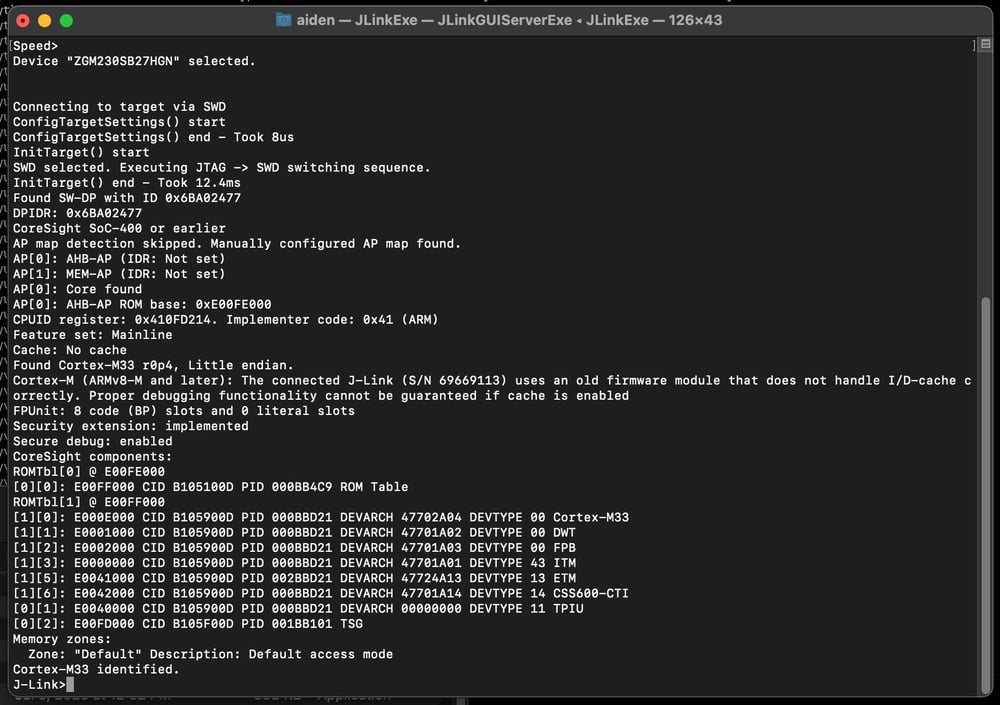
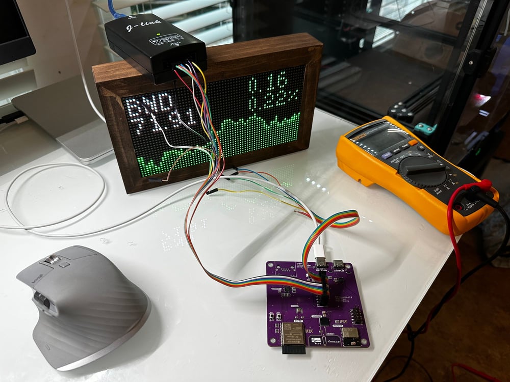
I attempted to use JLink Commander to connect to both of the radio modules, and while the Zigbee module responded on the first attempt, I actually had to use my hot air rework station to resolder the Z-Wave chip by hand with an unholy amount of flux.
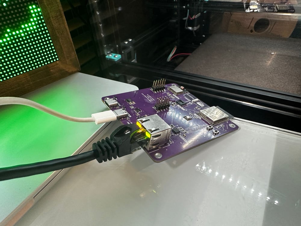
I soldered on the Ethernet jack and configured ESPHome to integrate with the LAN8720 PHY chip using the MDIO and MDC pins I used in the schematic, and to my immense surprise, it actually worked, and it had a 100Mbps link! I finally have to give some credit to the tools in Altium that ensure that the lengths of differential traces match up!
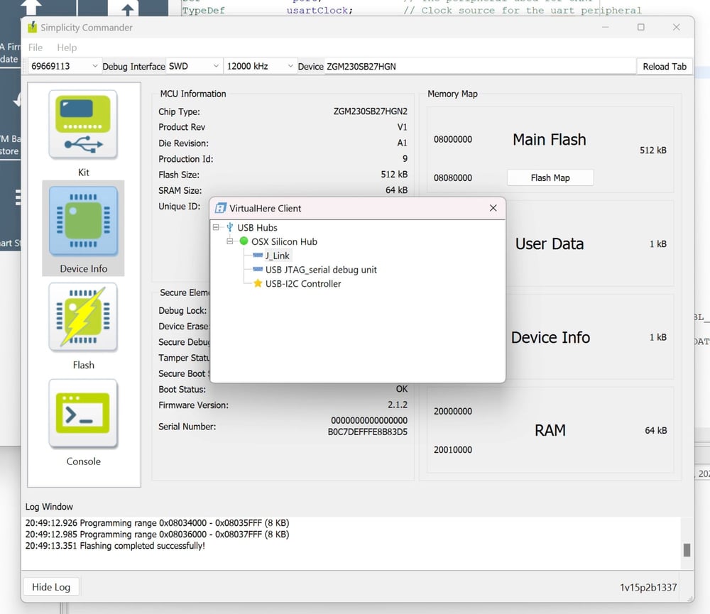
Silicon Labs, much like every other chip manufacturer in existence, ships their modules without a bootloader. This is great for a mass-produced product, but for just a one (or three) off run of boards, it's a pain to have to compile and flash the bootloaders using the JLink and Simplicity Studio. I actually had to switch over to my remote Windows box and use VirtualHere to share the J-Link over the network since the Mac version didn't include their flashing utility, Simplicity Commander.
I used the example solution provided to have the Z-Wave run a combination of the EZSP NCP UART API and the Gecko Bootloader, it just required a few configuration changes to enable Z-Wave LR and identify itself as an 800-series controller.
For the Zigbee/Thread side, things were a bit more difficult. I seperately built two projects, one for the Gecko Bootloader, and one for the Multiprotocol RCP firmware.
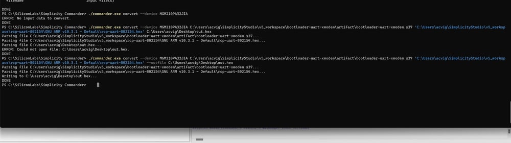
I used Simplicity Commander to turn both of these built files into one flashable image that I then flashed to the device using the JLink.
Problems ensue... :(
I wasn't seeing any activity over either of the CP2105's bridge ports, so I brought out my Saleae logic analyzer, and attempted to figure out what was wrong.
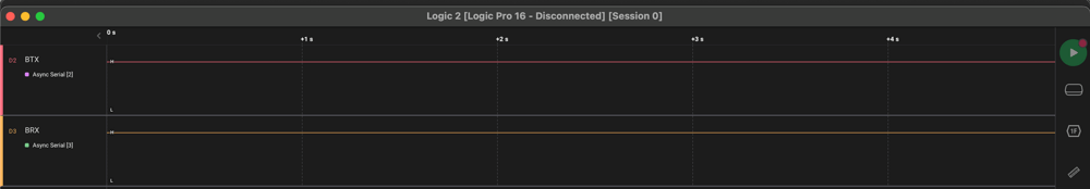
Both the TX and RX lines were completely dead. I poked around online and it turns out that Silabs' example projects use different bootloader & application UART pins than the ones mentioned in the datasheet. I eventually figured out where they were defined, and once I reflashed the modules, things were finally starting to happen.
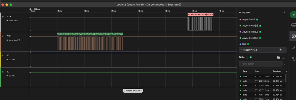
I was able to use the UART analyzer and the EZSP data sheet to confirm that everything was working properly on the radio side.
I also used the Logic software to troubleshoot an intermittent I2C bus issue that I had on one of the boards, due to a faulty pull-up resistor. Being able to see the exact transactions that are taking place make it extremely easy to pinpoint where the problem is coming from.
 Saleae
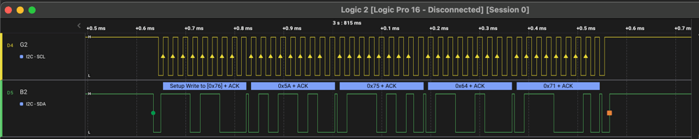
esphome:
  name: homehub
  friendly_name: homehub

esp32:
  board: esp32dev
  framework:
    type: arduino

bme680_bsec:

wireguard:
  address: 10.251.1.17
  private_key: #############
  peer_endpoint: !secret wireguard_endpoint
  peer_public_key: #############
  netmask: 255.255.255.0
  peer_preshared_key: #############
  peer_allowed_ips:
    - 10.251.1.17/24
  peer_persistent_keepalive: 25s

i2c:
  sda: 13
  scl: 12
  scan: true
  id: bus_a

# uart buses for ZGM230SA and MGM210P
uart:
- id: zwave
  baud_rate: 115200
  tx_pin: GPIO4
  rx_pin: GPIO5
- id: zigbee
  baud_rate: 115200
  tx_pin: GPIO14
  rx_pin: GPIO15

# stream servers
stream_server:
- id: ss_zw
  uart_id: zwave
  port: 8080
- id: ss_zb
  uart_id: zigbee
  port: 9090

binary_sensor:
  - platform: stream_server
    stream_server: ss_zw
    connected:
      name: zw conn
  - platform: stream_server
    stream_server: ss_zb
    connected:
      name: zb conn

sensor:
  - platform: bme680_bsec
    temperature:
      name: "BME680 Temperature"
    pressure:
      name: "BME680 Pressure"
    humidity:
      name: "BME680 Humidity"
    iaq:
      name: "BME680 IAQ"
      id: iaq
    co2_equivalent:
      name: "BME680 CO2 Equivalent"
    breath_voc_equivalent:
      name: "BME680 Breath VOC Equivalent"
yaml
Using external components for the TCP serial bridges and the WireGuard functionality, I was able to integrate my hub into ESPHome and avoid having to plug it into the device running Home Assistant. With WireGuard, I didn't even need it to be on the same network!
Using Bosch's BSEC environmental library, the raw data from the BME680 sensor gets converted into a calculated IAQ value which represents the indoor air quality.
GitHub • oxan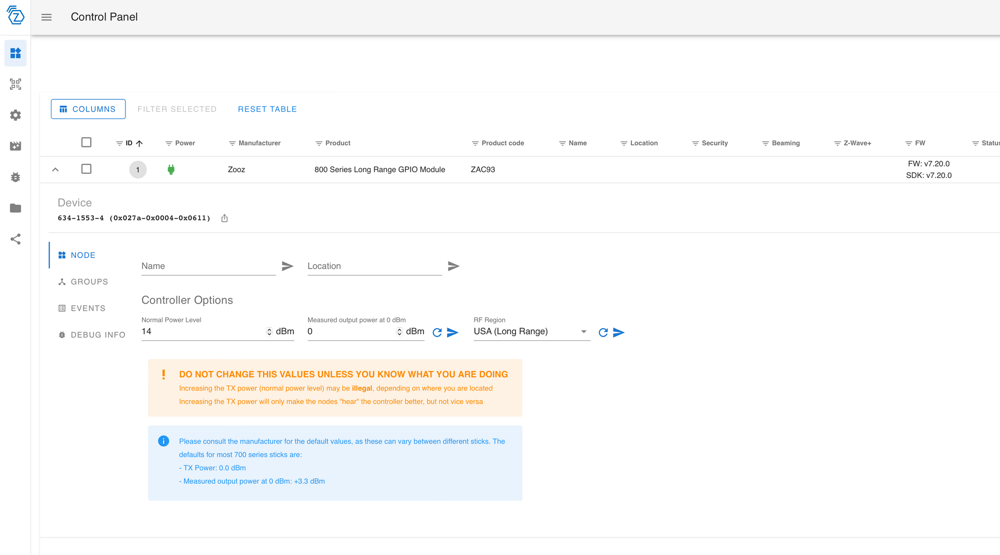
The addon ZWave JS UI has the option to use a TCP device as the radio's serial port, and it required zero setup! Home Assistant instantly saw the device and since I already configured the radio region & transmit power in Simplicity Studio, it imported all of the devices that I migrated over to the new radio!
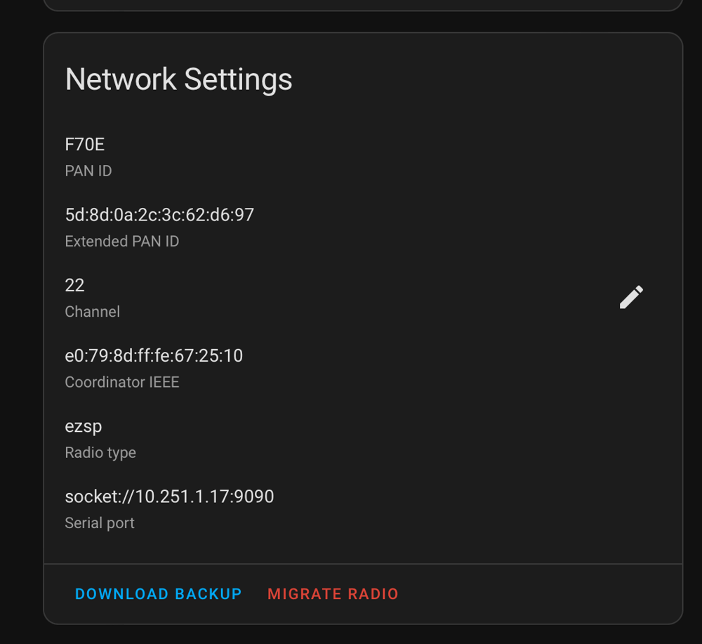
However, Zigbee was the problem child of the two. There's supposed to be an integrated migration feature that allows you to switch the radio device out without re-pairing every individual device, but it errored out. I had to dig out a HA backup from S3 and do a full restore which took a couple of hours. Second time around, it worked great!
I'm really happy with the outcome of this project, especially given the fact that I was able to upgrade an aging 500-series ZWave network to the latest 800-series standard, which actually enabled the removal of some range extenders due to the improved performance. While I don't have any Thread devices just yet, I feel much more prepared now that I already have a radio in place.
I've published all design files and precompiled firmware binaries to the repository linked below!
GitHub • acvigue