
The navigation system in my car stopped receiving updates, and I wanted a way to use Google Maps in my car by using CarPlay. I opened up Volvo VIDA to see how the radio was mounted, and it turns out that the radio actually manages the main fiber optics network in the car, so I needed to keep the radio.
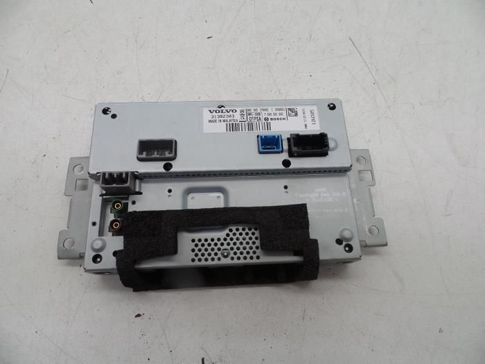
Taking a step back and thinking about it, I realized that the screen and radio PCB are in one unit (the ICM). If I could somehow extract the video signal from the ICM, I could install my own screen and switch to the original video signal whenever I wanted to.
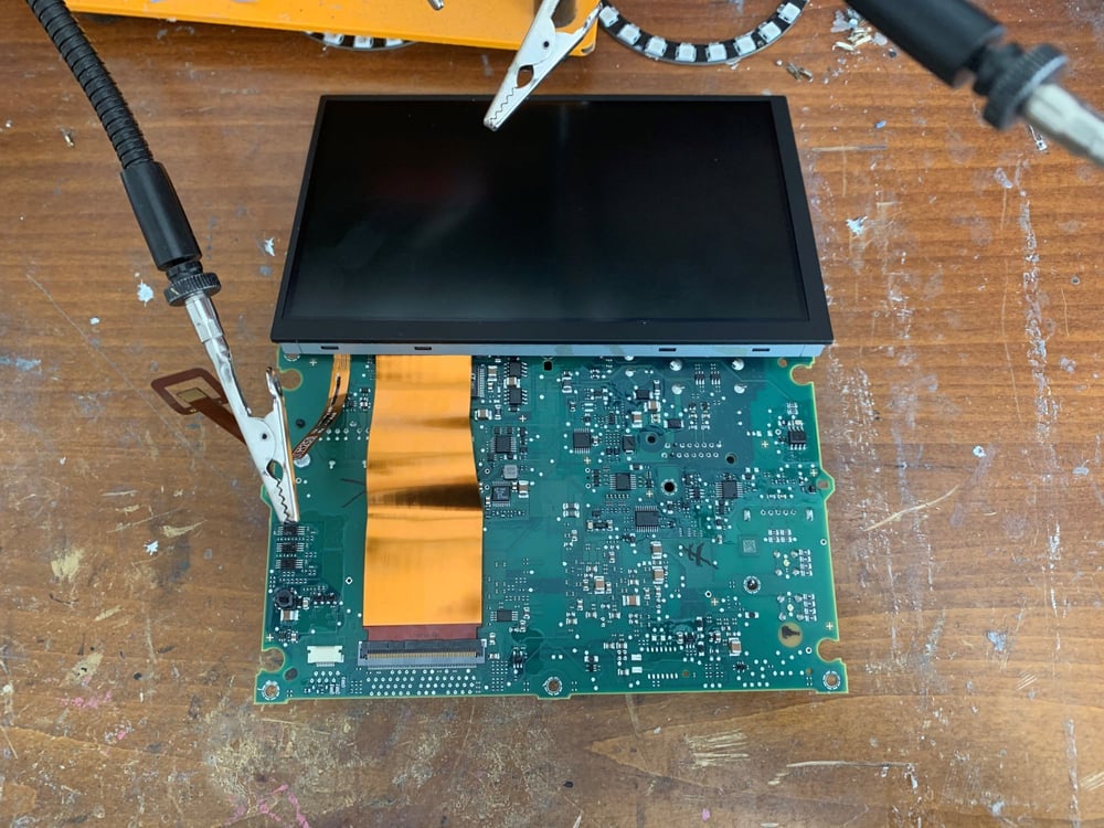
The screen seemed to be a standard RGB TTL screen with a 60-pin FPC cable, but I didn't know what the pinout was. I attempted to find a datasheet online, but since the panel is relatively old, I didn't find anything.
I realized that I would have to reverse engineer this and make my own datasheet. All of the pins were broken out right below the connector, so I started by finding power and ground in order to reduce the amount of pins I would have to search for the video signal on. I ended up with around half of them remaining, so I connected my logic analyzer and tried to find the video timing signals
TFT panels use four timing wires in addition to the pixel color input pins.
VSYNC - vertical sync (brought low for start of new frame)
HSYNC - horizontal sync (brought low for start of next line)
DE - data enable (ignore clock & pixel data when low)
CLK - pixel clock
The pixel clock and VSYNC were the easiest to find as they were changing states the fastest and slowest respectively. HSYNC and DE took a bit more effort to find, as they were only slightly different. Logically, DE would have to go low before HSYNC did, so I just had to look at the precise timing of when they went low.
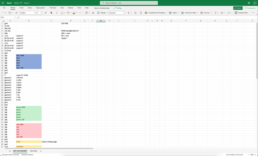
For the RGB pins, I got lazy and touched the remaining pins to VCC. Touching certain ones made the display more (or less) red, green, or blue, and from that it was easy to determine which pins were the most or least significant byte for each of the colors.
So, I opened up Excel and wrote down what I had found.
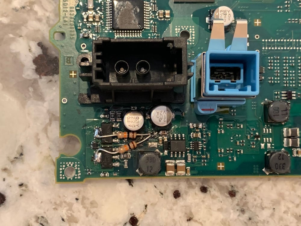
As I was putting the ICM back together, I didn't unplug the power and I shorted the back of the display to the motherboard and the magic smoke decided to come out. Thankfully, the only components that broke were two resistors for the transistors that drove the MOST bus. I was able to fix them by adding my own resistors.
With the display out of the way, I switched my focus to the steering wheel controls and the center console control buttons. The steering wheel communicated with the ICM using the LIN protocol. I spent some time figuring out how the different buttons on the steering wheel changed the data being sent over the bus.
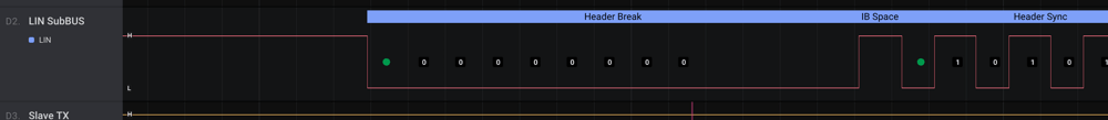
The steering wheel had two LIN IDs, 0x20 and 0x17. 0x20 handled the buttons, and 0x17 handled the LED backlighting behind the buttons.
The center console was connected to the main CAN bus, and I figured I could use a standard CAN to UART converter board.
I now had to design a PCB that I could connect to the ICM's video output port and convert the signals to HDMI. I also wanted to have an external HDMI input and be able to switch them using a HDMI switch IC. I found the TFP410 for converting the radio display signal, and I found a 2-port HDMI switch IC from TI. For the microcontroller, I chose the SAMD21, as it provided enough GPIO pins to work with the LIN transceivers and CAN bus module. I had to make two revisions of the board as the first one didn't really work.
This was the first "real" PCB I had ever made, and I learned a lot in the process of designing it. I designed it in Altium and really appreciated the almost nonexistent learning curve.
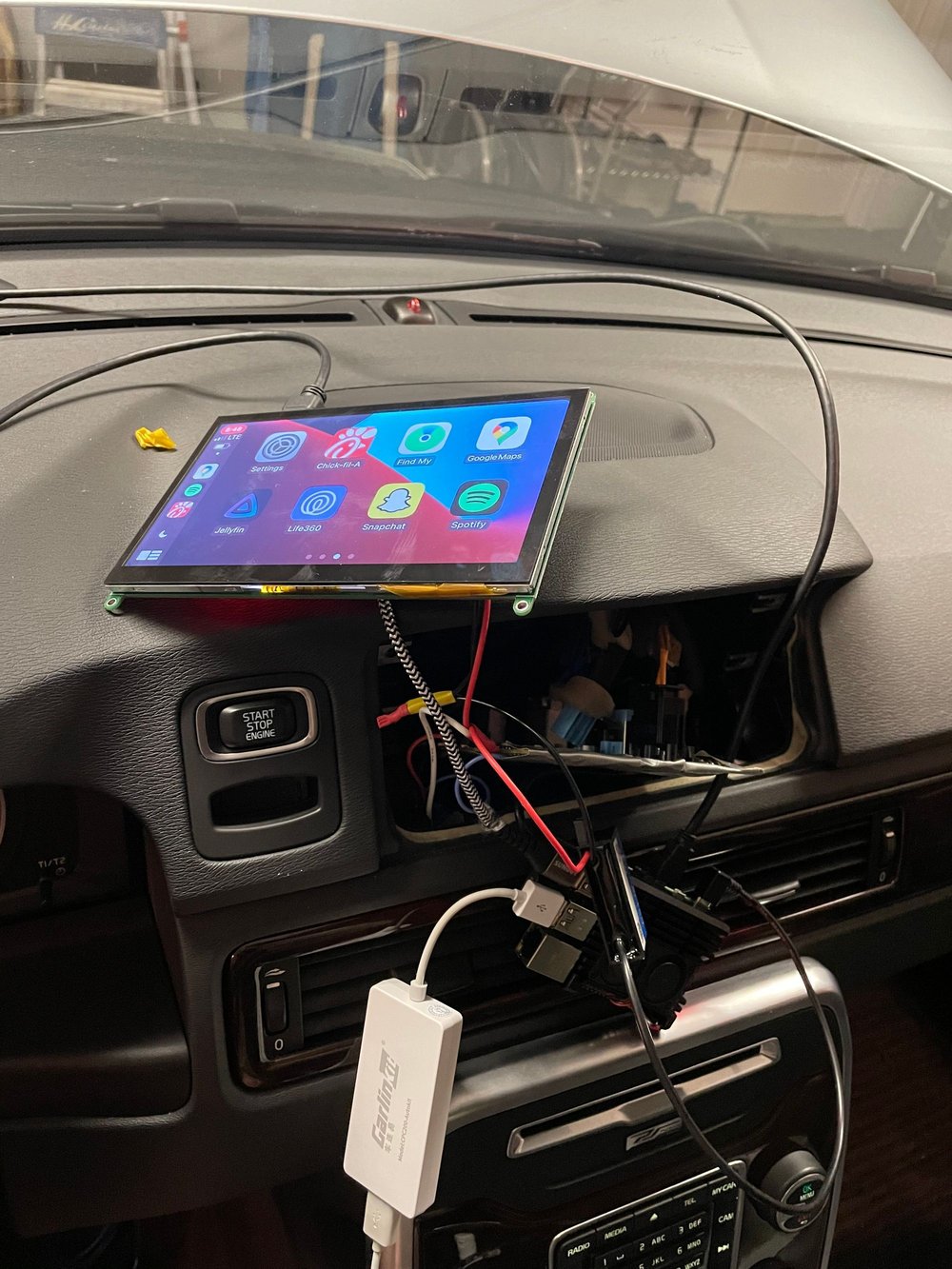
I now had to figure out how I was going to run CarPlay in the car. I had a spare Raspberry Pi, and I installed Android on it. To enable CarPlay functionality, I used the Carlinkit Autokit dongle. I played around with this setup for a bit and it worked great!
The LIN transceiver ICs communicated over UART and I wrote a small library that abstracted away functions such as checksum calculation and frame generation. The hardest part was having my board send packets back and forth fast enough between the steering wheel and ICM as I was basically MITMing the bus.
//Return requests for SWSR position - inner circle of hell.
  if(LinSlave.available() > 0) {
    //Check for valid synch byte (0x55)
    if(LinSlave.read() == 0x55) {
      delayMicroseconds(2200);
      byte h2 = LinSlave.read();
      //don't even get ID from pid bc i don't get paid enough
      //0x20 -> 0x21, 0x50 -> 0x17 in saleae
      //h2 = PID byte from frame (0x20 - SWSR, 0x50 - SWSR lighting)
      if(h2 == 0x20) {
        needCheckSWSR = true; //we need to send request to swsr to update our stored data

        //if we are in icm mode or if a button is pressed that requires handling via icm, send the data, else, send the base scroll flag data.
        if(needSendData == true || current_mode == MODE_ICM) {
          slave.writeResponse(current_swsr_data, 4);
        } else {
          slave.writeResponse(current_swsr_base, 4);
        }
      } else if(h2 == 0x50) {
      	//0x50 handles lighting, read the 3 data bytes from icm, and send them over master to swsr.
        delayMicroseconds(2000);
        uint8_t t1 = LinSlave.read();
        uint8_t t2 = LinSlave.read();
        uint8_t t3 = LinSlave.read();
        uint8_t currdta[3] = {t1,0x00,t3};
        master.writeRequest(0x10);
        LinMaster.write(currdta, 3);
      }
    }
  }
clike
I handled button presses from the center console using a CAN to UART board, and to free up some processing time on the MCU, I did all the message processing on the converter board itself. Now, my board only gets messages over UART whenever a button is pressed or if one of the aircon states change.
Now, the original Sensus infotainment OS shows little "modals" whenever the volume is turned up, or whenever the air settings are changed. I replicated these in CarPlay by having an always-running Android app that listened for messages sent by my board over USB and used the "draw over other apps" permission.
This project wasn't easy, but the outcome was totally worth it. I can switch between the two modes easily by holding the Exit button on the steering wheel. I learned a lot from this project, and it was the first time I had used a logic analyzer of any kind. I honestly wouldn't have been able to do this without it, I 100% recommend the Saleae to anyone.
I've have published the code for the Android app:
 GitHub • acvigue
the firmware for the SAMD21 chip:
GitHub • acvigueand the CAN bus converter board:
GitHub • acvigue